Simple Schematic Diagram Inverter Inverter Diagram Circuit 2
Sine wave inverter circuit diagram with full explanation Home made inverter circuit diagram 48vdc to 240vac inverter circuit diagram
48vdc To 240vac Inverter Circuit Diagram
Inverter mosfet 555 ne555 timer eleccircuit frequency sg3524 sine voltage volts schematics transformer generator figure1 12v How to build a 2kva inverter circuit diagram Inverter diy schematic circuit timer final square electronoobs circuitos
Inverter circuit wave sine sg3525 using modified 3525 ic protection low circuits output diagram power battery projects board control watt
Inverter diagram circuit 24v 2kva watt 2000 build schematics electrical board transformer simple schematic power wiring electronic dc ac panelOperation of 200 watt inverter diagram Diagram inverter circuit schematic 3000w ups watt function description powerInverter – diy electronics projects.
Tl494 inverter circuit 3000w complete video tutorial (12Simple inverter working principle Diy 555 inverter timer circuitUps circuit scematic.

Inverter circuit 500w, 12v to 220v
Inverter 1000wInverter circuit diagram 1000w power spwm 12v watt dc board 1000 driven inverters process volt source ts idea big Inverter circuit wave sine diagram board schematic power solar arduino full electronics projects inverters 1000w using diy 1kw charger icComplete circuit diagram of inverter.
12v to 220v inverter circuit diagram pdf downloadInverter 12v diagram circuit 220v dc ac sine wave 200w schematic schematics diagrams gif Inverter circuit diagram dc 12v to ac 220v 200w sine waveCircuit inverter 100w simple diagram.

15 transistor inverter circuit diagram
Ts big idea: 1000w power inverter circuit diagramSimple 100w inverter circuit Inverter tl494 220v 3000w power dc 5000w schematics voltage watts supplyWiring diagram for ups.
11+ simple inverter circuit diagram 1000w[diagram] stick diagram cmos inverter Inverter mosfet ne555 using power 220 circuit volts 555 diagram ic simple make timer 50hz wave output project use generatorModified sine wave inverter circuit using ic 3525, with regulated.
![Simple 100W Inverter Circuit - Working and Circuit Diagram [UPDATED]](https://i2.wp.com/www.circuitstoday.com/wp-content/uploads/2010/08/simple-100W-inverter-circuit.png)
Three phase inverter circuit diagram – diy electronics projects
Inverter circuits makingcircuits transistor newcomers 220vInverter principle circuit inverters 220v 12v eleccircuit 50hz Schematic diagram of the inverter.Inverter circuit diagram 1000w power spwm 12v watt dc 1000 board process inverters volt driven source.
Make simple 555 inverter circuit using mosfetPower inverter schematic circuit diagrams Inverter 500w 220v 220vac 24vdc 300w 24v elettrico volt circuits eleccircuit transformer pcb schematics daya invertor rangkaian modifying watt mosfetHomemade power inverter circuit diagram.

Diagram block inverter watt inverters 200watt operation circuits control eleccircuit output electronic projects two figure
Inverter generator schematic diagramInverter circuit diagram pdf Free energy inverter circuit diagramInverter circuit transformer simple watt 1000 project diagram transformerless phase diy three less electronics hub projects full.
12 volt 1000 watt power inverter design process .

![[DIAGRAM] Stick Diagram Cmos Inverter - MYDIAGRAM.ONLINE](https://i.ytimg.com/vi/nCbdMWc6MCU/maxresdefault.jpg)
[DIAGRAM] Stick Diagram Cmos Inverter - MYDIAGRAM.ONLINE

Wiring Diagram For Ups

Three Phase Inverter Circuit Diagram – DIY Electronics Projects
Inverter Circuit Diagram Pdf

Simple inverter working principle | ElecCircuit.com
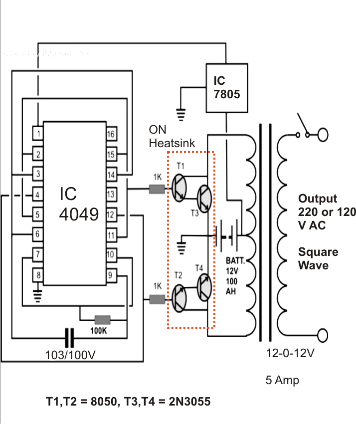
48vdc To 240vac Inverter Circuit Diagram

Inverter circuit 500w, 12V to 220V - ElecCircuit.com